Last week the final version of my work on developing a membraneless alkaline electrolyser was published in the chemical engineering journal (https://doi.org/10.1016/j.cej.2025.163444). This has been an accumulation of work completed during my time on the EPSRC Ocean Refuel project which was focused on understanding the management of bubbles in water electrolysers.
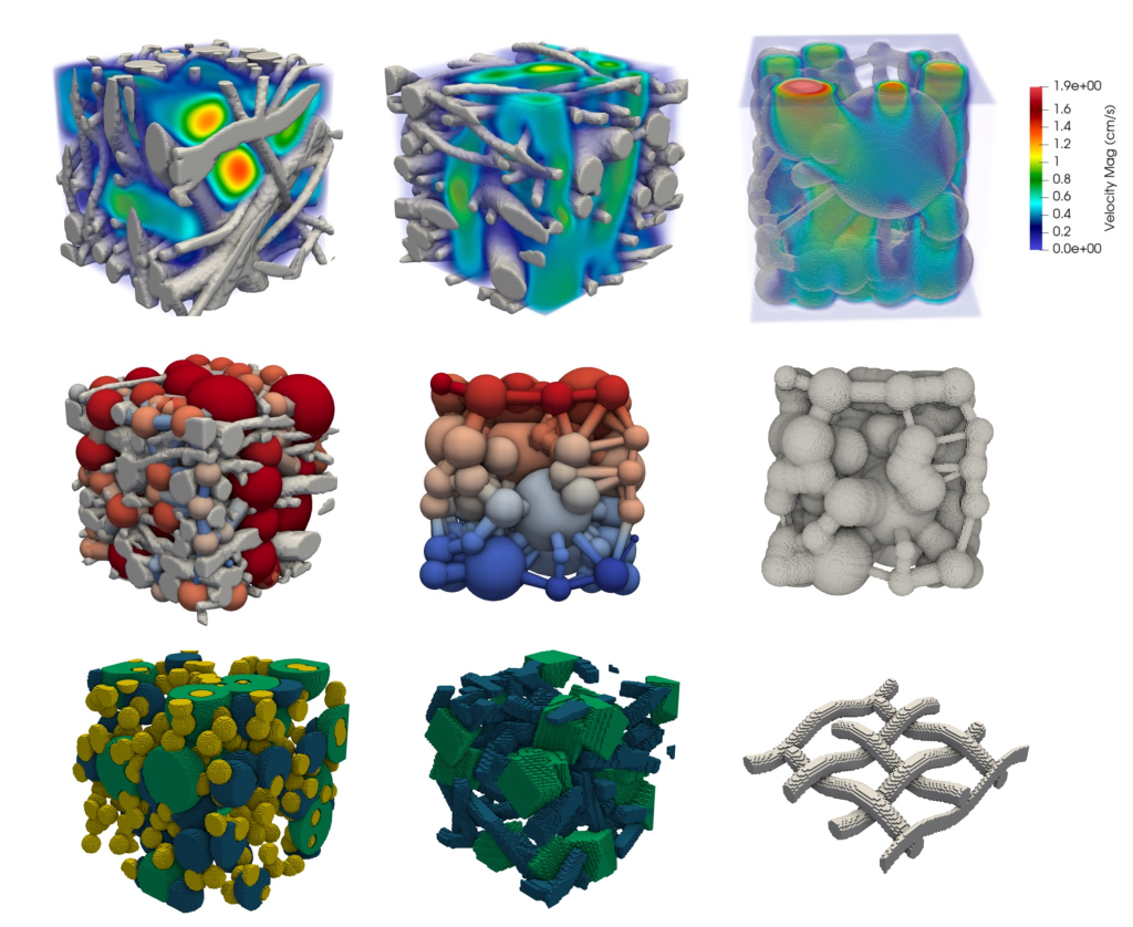
Part of this work was modelling; coupling two-phase flows (bubbles and electrolyte) and electrochemistry (ion transport and charge transfer) so that the distribution of bubbles could be known and their effect on the resistances in the system. For this purpose in OpenFOAM I coupled the volume-of-fluid method and solution of electrolyte potential to predict electrolyser performance as shown below:

This enabled prediction and understanding of how different electrodes or flow configurations would affect bubble distribution and device performance. The second part of this was the validation and fabrication, where similar to 2D simulations, we developed a 3D printed transparent pseudo-2D membraneless flow through electrolyser cell (where the fluid flows between electrodes) with a 2.1 mm electrode gap and nickel weave electrodes. By applying a small current (current density of <0.1 A/cm2) small bubbles were generated and could be used as tracer particles to track the flow distribution of the electrolyte. By applying particle image velocimetry to the videos (taken by high-speed camera Chronos-1.4) the fluid vectors could be extracted and compared to single-phase flow simulations (see below):

This was important to show that under some conditions, the flow may recirculate and be unfavourable for operation (since uniform flow through the electrodes is important to stop bubbles entering the middle channel). With reference to the simulations, a proper electrode arrangement was determined which restricted bubble formation between the electrode gap and this was verified by the high-speed camera videos at high current density (refer to the SI of the publication for video):
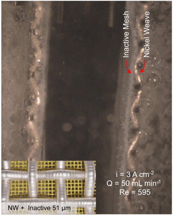
Although there was some defect within the construction (gap between the barrier layer and the porous electrode), this actually highlighted some operating features of the electrolyser. The capillary pressure barrier enabled confined flows to develop and even in the cases of gas saturated outlet chambers, the bubbles did not enter the electrode gap. Upon fixing the design and electrode, the dynamic profile of the potential during constant current showed a stable operation of 2.9 V at 1 A/cm2.
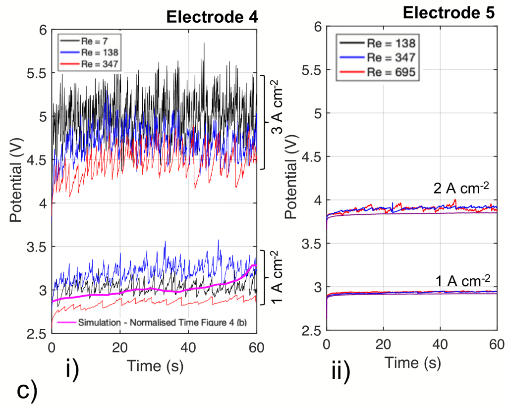
Further simulations highlighted that the current density distribution through the electrode is impacted by bubble formation and that the theoretical crossover of dissolved hydrogen in the system below 4% (from 0.01 – 0.5 m) is only possible with an inlet Reynolds number of greater than 50.

Although, without a proper design of the gas-liquid separator system with recycle, the electrolyser still had high dissolved gas crossover which will be addressed in the follow up scaling study. If you are interested further in this or to apply these methods for other purposes please let me know.